EPOS The Glob / Beastie Feastie / Eeekk! hardware encryption
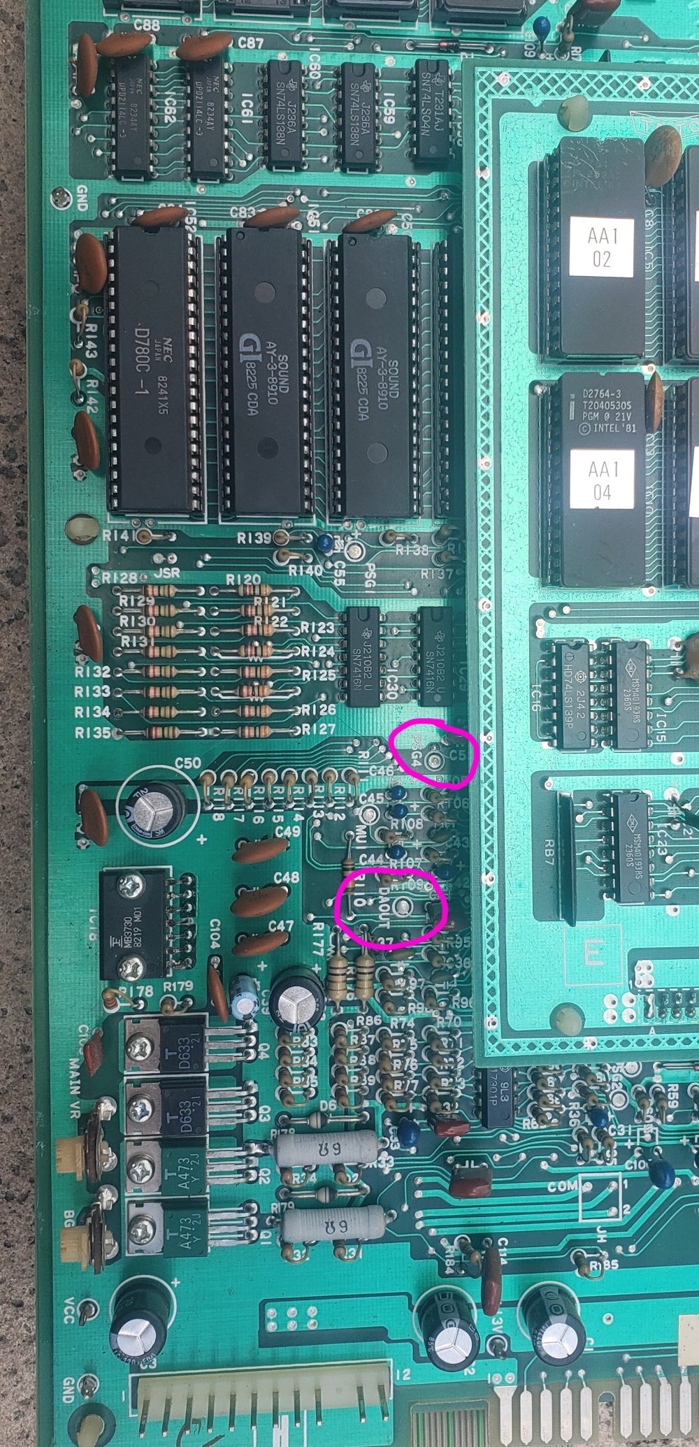
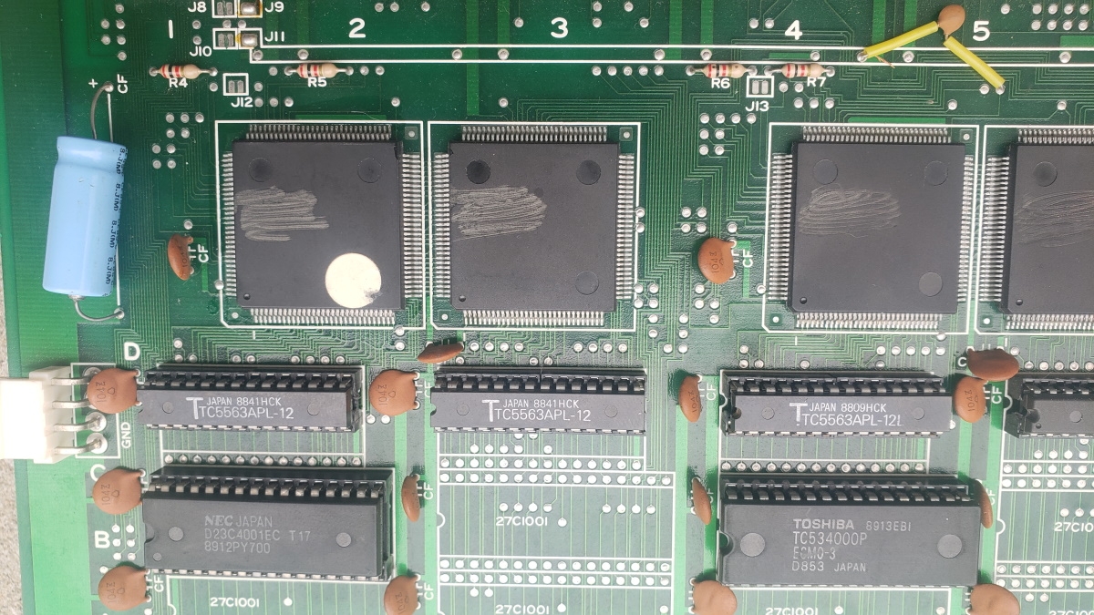
The EPOS games Glob, Super Glob, Beastie Feastie and Eeekk! run on Pacman hardware with a custom daughterboard. They use an obfuscated security system to prevent swapping the games just by burning the ROMs. Although these games are all emulated in MAME the security PAL chip for Beastie Feastie was not dumped until recently which meant the games couldn’t be repaired on real hardware until then (Although MAME had dumps for the PALs, they are all confirmed bad and did not work on real boards). The Eeekk! board is very rare and can not be found to be dumped, so I was asked if it’s possible to recreate the Eeeek! PAL based on the Beastie Feastie PAL and MAME information. And after some thought, yes…! Let’s see how.. this will get pretty technical though…


Part 1
First let’s look at the equations that come from the Beastie Feastie .JED file. ‘o’ means output (o19 = pin 19 on the PAL used for output). ‘i’ means input (i4 = pin 4 on the PAL used for input). / means invert/negate. * means AND. + means OR. Rather confusingly pin 11 is a double negative – it’s negated in the input section /i11=11 and negated everywhere it’s used in the equations.
i1=1 i2=2 i3=3 i4=4 i5=5 i6=6 i7=7 i8=8 i9=9 GND=10 /i11=11 o12=12

o13=13 o14=14 o15=15 o16=16 o17=17 o18=18 o19=19 VCC=20
o19 = /i4 * /i7 * /i9 * /i11
+ /i5 * i7 * /i9 * /i11
o18 = /i1 * /i8 * /i9 * /i11
+ /i6 * i8 * /i9 * /i11
o17 = i6 * /i8 * /i9 * /i11
+ /i3 * i8 * /i9 * /i11
o16 = /i2 * /i7 * /i9 * /i11
+ i4 * i7 * /i9 * /i11
o15 = /i3 * /i8 * /i9 * /i11
+ i1 * i8 * /i9 * /i11
o14 = i5 * /i7 * /i9 * /i11
+ /i2 * i7 * /i9 * /i11
/o13 = i9 * /i11
o12 = /i9 * /i11
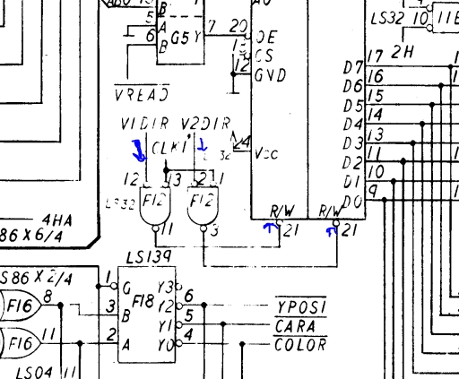
And the physical connections to the encryption PAL on the board:
PAL10H8 inputs
1: D7 from encrypted program ROM
2: D6 from encrypted program ROM
3: D4 from encrypted program ROM
4: D3 from encrypted program ROM
5: D1 from encrypted program ROM
6: D0 from encrypted program ROM
7: LS193 Q0
8: LS193 Q1
9: LS193 Q2
11: LS193 Q3
The LS193 is a 4 bit counter, that can provide a 4 bit (16 states) encryption key to the PAL. The program code can modify the counter state, which means the encryption can change dynamically as the program executes! In theory this means the program could be impossible to statically decrypt and run in the same amount of ROM as it can ‘read itself’ and each byte would have 16 permutations the code could rely on (in practice we’ll see later only 4 permutations are used). This is an interesting aspect to the original security – as to statically decrypt the 4 (or 16) states would mean using 4 or 16 times as many ROMs which would have been cost prohibitive for a commericial pirate.
Most of the outputs go to a LS244 buffer chip that passes through to the Z80 CPU.
19: o19 -> LS244 1A1 -> 1Y1 -> D7 Z80

17: o17 -> LS244 1A2 -> 1Y2 -> D5 Z80

15: o15 -> LS244 1A3 -> 1Y3 -> D3 Z80

14: o14 -> LS244 2A2 -> 2Y2 -> D2 Z80

16: o16 -> LS244 2A3 -> 2Y3 -> D4 Z80

18: o18 -> LS244 2A4 -> 2Y4 -> D6 Z80

12: o12 -> LS10 pin 1 (3 input NAND)

13: o13 -> LS10 pin 2 (3 input NAND)
So 6 of the 8 bits are decrypted by the PAL, and 2 of the bits go directly via a LS04 invertor. Outputs 12 & 13 seem to be involved in program ROM enable*, they are not involved in encryption and must be the same between all games for the enable circuit to work, so we don’t need to worry about them. (*Update from HudsonArcade – these drive the LS244 enables, the ROM select is just regular A13 from the CPU. Thanks!).
Let’s look at things from the LS244 point of view
PAL o19 -> 1A1 -> 1Y1 -> D7 Z80

PAL o17 -> 1A2 -> 1Y2 -> D5 Z80

PAL o15 -> 1A3 -> 1Y3 -> D3 Z80

(LS04 12) ->      1Y4 -> D1 Z80

(LS04 10) ->      2Y1 -> D0 Z80

PAL o14 -> 2A2 -> 2Y2 -> D2 Z80

PAL o16 -> 2A3 -> 2Y3 -> D4 Z80

PAL o18 -> 2A4 -> 2Y4 -> D6 Z80
We can rewrite the equations substituting the Z80 data lines and the key lines. I’ll also switch to use ‘C’ terminology (&& for and, || for OR, ! for negate), as I think in C++…
o14 = (D1 && !KEY0 && !KEY2 && !KEY3) || (!D6 && KEY0 && !KEY2 && !KEY3)

o15 = (!D4 && !KEY1 && !KEY2 && !KEY3) || (D7 && KEY1 && !KEY2 && !KEY3)

o16 = (!D6 && !KEY0 && !KEY2 && !KEY3)  || (D3 && KEY0 && !KEY2 && !KEY3)

o17 = (D0 && !KEY1 && !KEY2 && !KEY3) || (!D4 && KEY1 && !KEY2 && !KEY3)

o18 = (!D7 && !KEY1 && !KEY2 && !KEY3) || (!D0 && KEY1 && !KEY2 && !KEY3)

o19 = (!D3 && !KEY0 && !KEY2 && !KEY3) || (!D1 && KEY0 && !KEY2 && !KEY3)
If we remove the key bits we can see each output bit depends on two input bits
o14 = D1 || !D6

o15 = !D4 || D7

o16 = !D6 || D3

o17 = D0 || !D4

o18 = !D7 || !D0

o19 = !D3 || !D1
And let’s rewrite the equations another way to show what ROM bits attach to what Z80 bits.
Z80 D0 comes from LS04 pin 12

Z80 D1 comes from LS04 pin 10

Z80 D2 must be D1 or !D6 from the ROM (o14 in PAL)

Z80 D3 must be !D4 or D7 from the ROM

Z80 D4 must be !D6 or D3

Z80 D5 must be D0 or !D4

Z80 D6 must be !D7 or !D0

Z80 D7 must be !D3 or !D1
Part 2
Let’s reconcile this with MAME source. machine/epos.cpp
MACHINE_START_MEMBER(pacman_state, theglobp)

{

	/*  Note: D2 is inverted and connected to D1, D5 is inverted and

	connected to D0.  The other six data bits are converted by a

	PAL10H8 driven by the counter. */
This matches so far – D0 and D1 are noted to be inversions (LS04) of D2 and D5 from ROM data. D2 and D5 aren’t used by the PAL. The counter is the LS193 chip that supplies a 4 bit input to the PAL.
/* While the PAL supports up to 16 decryption methods, only four

	are actually used in the PAL.  Therefore, we'll take a little

	memory overhead and decrypt the ROMs using each method in advance. */
MAME notes that although the counter can supply 16 states (4 bits) only 4 states are used by the games, corresponding to counter states 0×8, 0×9, 0xa, 0xb
MAME lists the bit swizzle order for the 4 states as:
		{ 3,7,0,6,4,1,2,5 },

		{ 1,7,0,3,4,6,2,5 },

		{ 3,0,4,6,7,1,2,5 },

		{ 1,0,4,3,7,6,2,5 },
although confusingly this table is ‘backwards’ with D7 first and D0 last (so the 5 at the end of the row refers to D5 connecting to D0, the 2 second most from right refers to ‘D2 inverted and connected to D1′). If we can scan the columns we can see that each bit can only have 1 or 2 input bits (the first column is 3 or 1, the second column is 7 or 0). Now we can confirm MAME data matches the PAL equations if we refer back to the Z80 form equations:
The first column (D7) uses only bits 1 or 3 which matches ‘Z80 D7 must be !D3 or !D1′
The second column (D6) uses only bits 7 or 0 which matches ‘Z80 D6 must be !D7 or !D0′
The third column (D5) uses only bits 0 or 4 which matches ‘Z80 D5 must be D0 or !D4′
etc
Looking at the equations again, every output contains depends on 3 of the 4 input keys. And the 3rd and 4th input key is identical between all outputs, so we can pretty much ignore it and say each output only depends on 2 input keys. This is where the 4 states in MAME come from.
Let’s work through state 0×8 which MAME notes uses this bit swizzle order – { 3,7,0,6,4,1,2,5 } and inversion (XOR) of 0xfc. Encryption state 0×8 means the key is:
KEY0 = 0 (low / false)
KEY1 = 0 (low / false)
KEY2 = 0 (low / false)
KEY3 = 1 (high / true) (remember key input i11 has a double negation from part 1!)
Rewrite the Z80 equation for D2 with this set of input keys:
Z80 D2 IN = (D1 && !KEY0 && !KEY2 && !!KEY3) || (!D6 && KEY0 && !KEY2 && !!KEY3)

Z80 D2 IN = (D1 && !0 && !0 && !!0) || (!D6 && 0 && !0 && !!0)

Z80 D2 IN = (D1 && 1 && 1 && 1) || (!D6 && 0 && 1 && 1)

Z80 D2 IN = (D1 && 1 && 1 && 1)

Z80 D2 IN = (D1)
So D2 at the Z80 is D1 from the encrypted ROM with no inversion
When the key state is 0xb:
KEY0 = 1
KEY1 = 1
KEY2 = 0
KEY3 = 1
Z80 D2 IN = (D1 && !KEY0 && !KEY2 && !!KEY3) || (!D6 && KEY0 && !KEY2 && !!KEY3)

Z80 D2 IN = (D1 && !1 && !0 && !!0) || (!D6 && 1 && !0 && !!0)

Z80 D2 IN = (D1 && 0 && 1 && 1) || (!D6 && 1 && 1 && 1)

Z80 D2 IN = (!D6 && 1 && 1 && 1)

Z80 D2 IN = !D6
So D2 is inverted D6 for this key.
So this matches the table in MAME (the 3rd column from the right being D2 and it contains the values 1 and 6). The MAME xor key is used to mask the inversions.
All of the 6 input bits can be solved for all 4 keys in the same way. And KEY2 and KEY3 can effectively be ignored as they are constant in all equations.
Part 3
Now we can attempt to build the Eeek equations based on MAME knowledge. The 4 swizzle tables are:
-
{ 7,6,1,3,0,4,2,5 },
{ 7,1,4,3,0,6,2,5 },
{ 7,6,1,0,3,4,2,5 },
{ 7,1,4,0,3,6,2,5 },
So we can break this down by walking the columns:
-
Z80 D7 can only ever come from ROM D7
Z80 D6 can only ever come from ROM D6 or D1
Z80 D5 can only ever come from ROM D1 or D4
Z80 D4 can only ever come from ROM D3 or D0
Z80 D3 can only ever come from ROM D0 or D3
Z80 D2 can only ever come from ROM D4 or D6
Z80 D0 can only ever come from ROM D2
Z80 D1 can only ever come from ROM D5
Based on the Beastie Feastie knowledge, we can work out what keys influence what bits.
-
Z80 D7 is constant – does not care what key 0 or key 1 is.
Z80 D6 depends on key 0, does not care what key 1 is
Z80 D5 depends on key 0, does not care what key 1 is
Z80 D4 depends on key 1, does not care what key 0 is
Z80 D3 depends on key 1, does not care what key 0 is
Z80 D2 depends on key 0, does not care what key 1 is
Z80 D1 is constant – does not care what key 0 or key 1 is.
Z80 D0 is constant – does not care what key 0 or key 1 is.
Put these things together, and add in the constant KEY2 and KEY3 terms (though the game will surely work if we just emit them).
-
Z80 D7 = (D7 && !KEY2 && !KEY3)
Z80 D6 = (D6 && !KEY0 && !KEY2 && !KEY3) || (D1 && KEY0 && !KEY2 && !KEY3)
Z80 D5 = (D1 && !KEY0 && !KEY2 && !KEY3) || (D4 && KEY0 && !KEY2 && !KEY3)
Z80 D4 = (D3 && !KEY1 && !KEY2 && !KEY3) || (D0 && KEY1 && !KEY2 && !KEY3)
Z80 D3 = (D0 && !KEY1 && !KEY2 && !KEY3) || (D3 && KEY1 && !KEY2 && !KEY3)
Z80 D2 = (D4 && !KEY0 && !KEY2 && !KEY3) || (D6 && KEY0 && !KEY2 && !KEY3)
Z80 D1 = (D2 && !KEY2 && !KEY3)
Z80 D0 = (D5 && !KEY2 && !KEY3)
Now we have apply the inversion terms which MAME lists in hex for the 4 tables, but are easier to understand in binary:
-
key 0 – 0xfd = 1111 1101
key 1 – 0xbf = 1011 1111
key 2 – 0×75 = 0111 0101
key 3 – 0×37 = 0011 0111
So D7 is inverted in key states 0 and 1, and non-inverted in 2 & 3. D6 is inverted in key states 0 and 2, non-inverted in 1 & 3. So if we walk the columns we can say:
-
D7 inversion depends on key 1
D6 inversion depends on key 0
D5 inversion is constant (same for all key states)
D4 inversion is constant (same for all key states)
D3 inversion depends on key 1
D2 inversion is constant (same for all key states)
D1 inversion depends on key 0
D0 inversion is constant (same for all key states)
As a sanity check we can see that where there is a key dependency it matches the key influence above.
Rewrite the equations to add inversions:
-
Z80 D7 = (!D7 && !KEY1 && !KEY2 && !KEY3) || ( D7 && KEY1 && !KEY2 && !KEY3)
Z80 D6 = (!D6 && !KEY0 && !KEY2 && !KEY3) || (!D1 && KEY0 && !KEY2 && !KEY3)
Z80 D5 = ( D1 && !KEY0 && !KEY2 && !KEY3) || (!D4 && KEY0 && !KEY2 && !KEY3)
Z80 D4 = (!D3 && !KEY1 && !KEY2 && !KEY3) || (!D0 && KEY1 && !KEY2 && !KEY3)
Z80 D3 = (!D0 && !KEY1 && !KEY2 && !KEY3) || ( D3 && KEY1 && !KEY2 && !KEY3)
Z80 D2 = (!D4 && !KEY0 && !KEY2 && !KEY3) || ( D6 && KEY0 && !KEY2 && !KEY3)
Z80 D1 = (!D2 && !KEY2 && !KEY3)
Z80 D0 = (!D5 && !KEY2 && !KEY3)
Now rewrite back to the PAL’s point of view rather than the Z80, so D7 is PAL o19, D5 is pal o17, etc
-
PAL o19 = (!D7 && !KEY1 && !KEY2 && !KEY3) || ( D7 && KEY1 && !KEY2 && !KEY3)
PAL o18 = (!D6 && !KEY0 && !KEY2 && !KEY3) || (!D1 && KEY0 && !KEY2 && !KEY3)
PAL o17 = ( D1 && !KEY0 && !KEY2 && !KEY3) || (!D4 && KEY0 && !KEY2 && !KEY3)
PAL o16 = (!D3 && !KEY1 && !KEY2 && !KEY3) || (!D0 && KEY1 && !KEY2 && !KEY3)
PAL o15 = (!D0 && !KEY1 && !KEY2 && !KEY3) || ( D3 && KEY1 && !KEY2 && !KEY3)
PAL o14 = (!D4 && !KEY0 && !KEY2 && !KEY3) || ( D6 && KEY0 && !KEY2 && !KEY3)
D0 and D1 are not affected by the PAL, so we can ignore them.
Rewrite back to the JED format we can use with the hardware, with the mapping from before:
-
i1: D7 from ROM
i2: D6 from ROM
i3: D4 from ROM
i4: D3 from ROM
i5: D1 from ROM
i6: D0 from ROM
i7: LS193 Q0 / Key 0
i8: LS193 Q1 / Key 1
i9: LS193 Q2 / Key 2
i11: LS193 Q3 / Key 3
o19 = /i1 * /i8 * /i9 * /i11
+ i1 * i8 * /i9 * /i11
o18 = /i2 * /i7 * /i9 * /i11
+ /i5 * i7 * /i9 * /i11
o17 = i5 * /i7 * /i9 * /i11
+ /i3 * i7 * /i9 * /i11
o16 = /i4 * /i8 * /i9 * /i11
+ /i6 * i8 * /i9 * /i11
o15 = /i6 * /i8 * /i9 * /i11
+ i4 * i8 * /i9 * /i11
o14 = /i3 * /i7 * /i9 * /i11
+ i2 * i7 * /i9 * /i11
/o13 = i9 * /i11
o12 = /i9 * /i11
o12 and o13 we’ll leave alone as they aren’t involved in encryption and must be the same between all games.
Part 4
The final EQN file – this can be burned to a GAL16V8 and used on the original hardware. The 4 jumpers on the board must also be set to match the game. The 4 jumpers actually correspond to the default key the game boots in (from the 0×8, 0×9, 0xa, 0xb) counter states. Glob boots in state 0xa (top to bottom jumpers on, off, on, off) whilst Eeekk boots in state 0×9 (off, on, on, off)
; JED2EQN -- JEDEC file to Boolean Equations disassembler (Version V063)

; Copyright (c) National Semiconductor Corporation 1990-1993

; Disassembled from BEASTIE.JED. Date: 1-5-123

;$GALMODE SMALL
chip EEEK GAL16V8
i1=1 i2=2 i3=3 i4=4 i5=5 i6=6 i7=7 i8=8 i9=9 GND=10 /i11=11 o12=12
o13=13 o14=14 o15=15 o16=16 o17=17 o18=18 o19=19 VCC=20
@ues 0000000000000000
@ptd unused
equations
o19 = /i1 * /i8 * /i9 * /i11
+ i1 * i8 * /i9 * /i11
o18 = /i2 * /i7 * /i9 * /i11
+ /i5 * i7 * /i9 * /i11
o17 = i5 * /i7 * /i9 * /i11
+ /i3 * i7 * /i9 * /i11
o16 = /i4 * /i8 * /i9 * /i11
+ /i6 * i8 * /i9 * /i11
o15 = /i6 * /i8 * /i9 * /i11
+ i4 * i8 * /i9 * /i11
o14 = /i3 * /i7 * /i9 * /i11
+ i2 * i7 * /i9 * /i11
/o13 = i9 * /i11
o12 = /i9 * /i11


Recent Comments